Re: Removing Ring Artefacts
Posted by pcloetens on Oct 01, 2008; 6:24pm
URL: http://imagej.273.s1.nabble.com/Removing-Ring-Artefacts-tp3694905p3694907.html
http://rsbweb.nih.gov/ij/plugins/polar-transformer.html
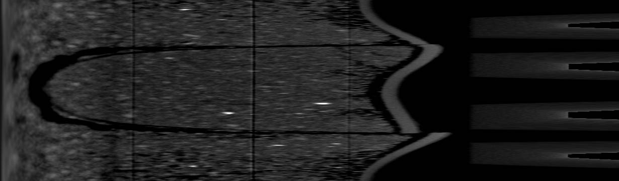
After transforming to polar coordinates, the rings will appear as vertical lines. The basic idea is that it will be easier to separate these vertical lines from the object information. After filtering the vertical lines in some way, it is sufficient to go back to cartesian coordinates. I made a quick trial on the soil image. As filtering I used an horizontal average on a (manual !) selection of each vertical line. The main steps are recorded below. Maybe this can help as a starting point.
Peter
Some results:
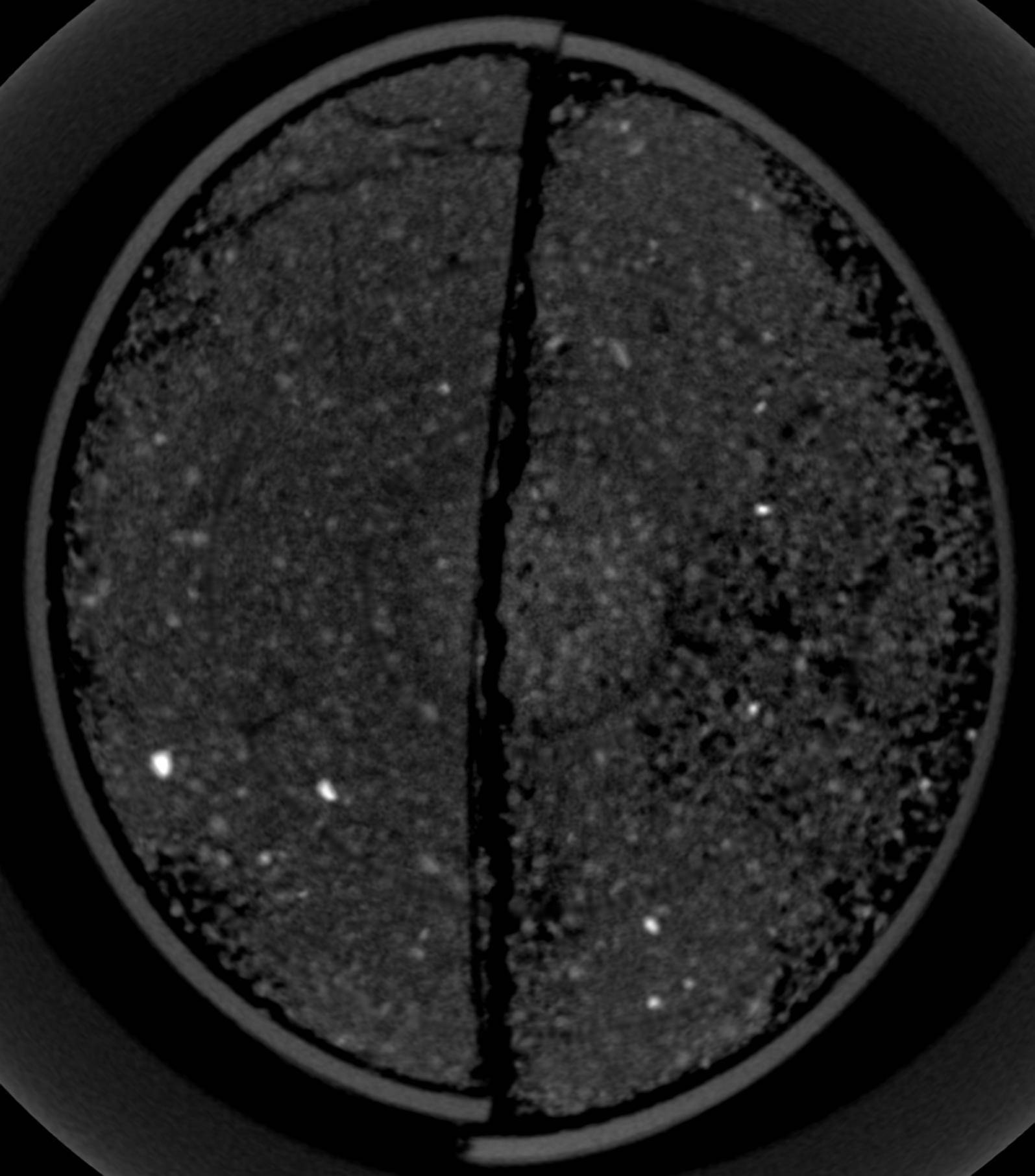
Corrected image:
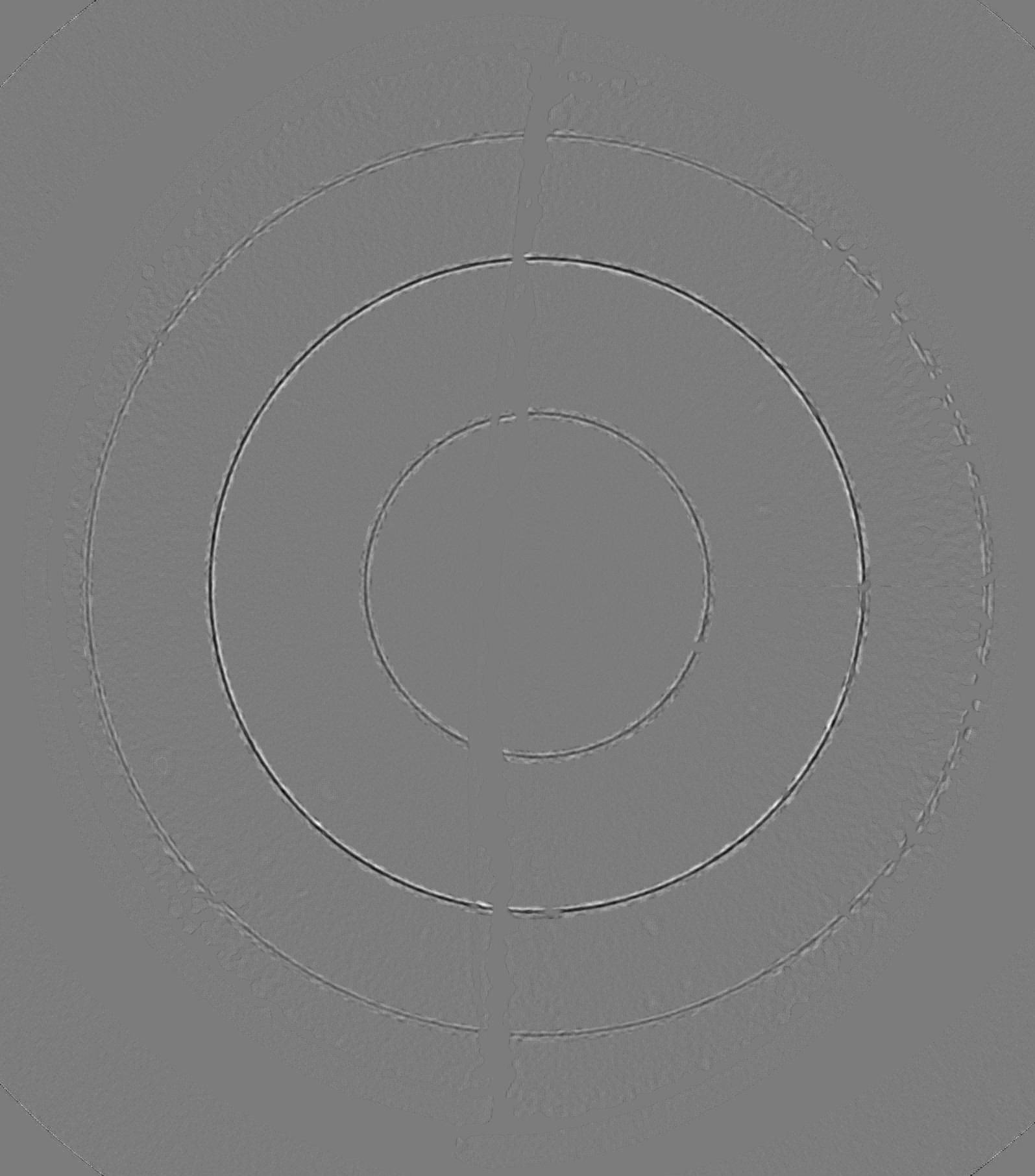
Difference:
Polar transform (360 angles instead of the 1500 used):
run("Polar Transformer", "method=Polar degrees=360 number=1500 center=827.4 center=902.4");
FILTER ON MANUAL SELECTION AROUND VERTICAL LINE
run("Convolve...", "text1=[1 1 1 1 1 1 1 1 1\\n] normalize");
run("Polar Transformer", "method=Cartesian degrees=360 for center=827.4 center=902.4");
run("Specify...", "width=1595 height=1813 x=0 y=0");
run("Crop");
URL: http://imagej.273.s1.nabble.com/Removing-Ring-Artefacts-tp3694905p3694907.html
Ring artifacts are common on all real world CT image systems. They correspond for example to defects of the detector. The artifact will be at a fixed position on the projections and thus form a circle (360 degrees scan) or half circle (180 degrees scan) on the tomographic slice. The best solution is to avoid these artifacts at the source or to correct on the projections. In case only reconstructed slices are available several methods are proposed in the literature. A good starting point in ImageJ could be the polar transform and its inverse:
http://rsbweb.nih.gov/ij/plugins/polar-transformer.html
After transforming to polar coordinates, the rings will appear as vertical lines. The basic idea is that it will be easier to separate these vertical lines from the object information. After filtering the vertical lines in some way, it is sufficient to go back to cartesian coordinates. I made a quick trial on the soil image. As filtering I used an horizontal average on a (manual !) selection of each vertical line. The main steps are recorded below. Maybe this can help as a starting point.
Peter
Some results:
Corrected image:
Difference:
Polar transform (360 angles instead of the 1500 used):
run("Polar Transformer", "method=Polar degrees=360 number=1500 center=827.4 center=902.4");
FILTER ON MANUAL SELECTION AROUND VERTICAL LINE
run("Convolve...", "text1=[1 1 1 1 1 1 1 1 1\\n] normalize");
run("Polar Transformer", "method=Cartesian degrees=360 for center=827.4 center=902.4");
run("Specify...", "width=1595 height=1813 x=0 y=0");
run("Crop");
| Free forum by Nabble | Disable Popup Ads | Edit this page |