Leveling Image

12
12

|
Hello Everyone
I would really appreciate if someone could guide me that what is the best method to bring the whole image to the same level. Its like I have images in which Small surface corrugations can sometimes be dominated by the noise in the scanner system. Typically, this creates observable steps between subsequent scan lines. Likewise, temporary contamination of the probe will cause the scan lines to be leveled differently. How can I bring the scan lines to more probable level. I appreciate your help Regards Ahsan |
|
|
On Monday 22 Aug 2011, you wrote:
> I would really appreciate if someone could guide me that what is the best > method to bring the whole image to the same level. Its like I have images > in which Small surface corrugations can sometimes be dominated by the > noise in the scanner system. Typically, this creates observable steps > between subsequent scan lines. Likewise, temporary contamination of the > probe will cause the scan lines to be leveled differently. How can I bring > the scan lines to more probable level. It is nearly impossible to give useful advice without seeing what your images look like. I imagine that if the images have areas of "background" that appear in all scan lines, and the background is expected to appear constant, you could identify which pixels in each scan line are the background (or part of it) to get their mean to offset the grey values of the whole line so the background pixels all have the same mean. But maybe this is not enough as there might be a multiplicative effect, in which case you need to do something more than adding/subtracting an offset. Most importantly you need a better method of image capture or get the scanner serviced. Post processing can only do certain things. If the change of intensity is random (and constant for each line), then you could increase the scanning speed and capture more images, then integrate/average them in the hope that the random variations average out over several shots (this noise suppression factor would be about the sqrt(images) ). But perhaps the artifacts you get change the intensity as the line is scanned, which would make the whole thing much more complicated. Cheers Gabriel |
|
|
In reply to this post by ashamim
Hi,
this happens frequently in AFM (atomic force microscopy)! My first step in the direction of correction was therefor to look at or to use the freeware program WSxM for SPM (scanning probe microscopy) from http://www.nanotec.es/ (http://www.nanotec.es/products/wsxm/index.php). Of course this is only a hint to get some ideas or to see some of what already exists. It is necessary to define a model for the "most probable level" and correct the scan lines according this model. This is a typical application of ImageJ! Regards Karsten Am 22.08.2011 um 10:08 schrieb ashamim: > Hello Everyone > > I would really appreciate if someone could guide me that what is the best > method to bring the whole image to the same level. Its like I have images in > which Small surface corrugations can sometimes be dominated by the noise in > the scanner system. Typically, this creates observable steps between > subsequent scan lines. Likewise, temporary contamination of the probe will > cause the scan lines to be leveled differently. How can I bring the scan > lines to more probable level. > > I appreciate your help > > Regards > > Ahsan > > ----- > Ahsan > -- > View this message in context: http://imagej.588099.n2.nabble.com/Leveling-Image-tp6710546p6710546.html > Sent from the ImageJ mailing list archive at Nabble.com. Karsten [hidden email] |
|
|
In reply to this post by Gabriel Landini
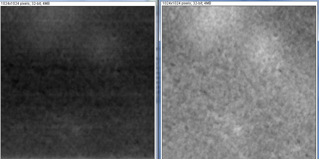 Gabriel Thank so much for the reply. I really appreciate that. I have attached the sample image. The image on the left is what I have and the image on the right is what i want. Beside the contrast of the image there are prominent lines in horizontal direction (dark) in the image on the left. These are the lines because of the different levels. Regards Ahsan |
|
|
In reply to this post by karo03
Karsten
Thanks for the reply. I'll just look into the link to get some help. Regards |
|
|
In reply to this post by ashamim
Hi Ahsan,
your image looks like an application for Process>FFT>Bandpass filter with only "Remove Stripes" with a small low angular tolerance and an infinite bandpass ('Small structures:' 0, 'Large structures:' An number much larger than the side length of the image in pixels, e.g. 1e6.) It is best to convert the image to float (32 bit) before, then you can disable the 'autoscale' and 'saturate' options. This filter essentially subtracts a line-by-line background. For some scanning probe microscopy images an even better option would be to subtract not the mean but rather the median of each line (after subtracting a plane); maybe someone knows about such a plugin. Michael ________________________________________________________________ On 22 Aug 2011, at 12:34, ashamim wrote: > http://imagej.588099.n2.nabble.com/file/n6710969/sample.jpg > > Gabriel > > Thank so much for the reply. I really appreciate that. I have > attached the > sample image. The image on the left is what I have and the image on > the > right is what i want. Beside the contrast of the image there are > prominent > lines in horizontal direction (dark) in the image on the left. > These are the > lines because of the different levels. > > Regards > > Ahsan > > > ----- > Ahsan > -- > View this message in context: http://imagej.588099.n2.nabble.com/ > Leveling-Image-tp6710546p6710969.html > Sent from the ImageJ mailing list archive at Nabble.com. |
|
|
Michael
Thank you much for you reply. The approach you talked about in the end is actually what i am thinking and looking for. I.e. first subtracting a fitted plane to remove the noise and then correcting the image line by line by using the median approach. I have been able to do the plane correction and was wondering if there is any plugin for line wise correction using the median approach. Kind regards Ahsan |
|
|
On Monday 22 Aug 2011, Ahsan wrote:
> Thank you much for you reply. The approach you talked about in the end is > actually what i am thinking and looking for. I.e. first subtracting a > fitted plane to remove the noise and then correcting the image line by > line by using the median approach. I have been able to do the plane > correction and was wondering if there is any plugin for line wise > correction using the median approach. The Fourier analysis image looks truly impressive, but wouldn't this erase areas that also happen to be originally dark and horizontal? I wonder if this would be unable to differentiate between the artifact and the data. For example is the horizontal dark valley in the original a feature or an artifact? Now that you provided an image, the idea of modelling the background intensity goes through the window as there is no obvious background in the image to play with. To answer your other question, to do a line filtering you can reslice your image (from Top). This creates a stack which is the image seen from the top (so each slice is a line). Then you could filter the stack with a median filter as large as the image width and reslice back to obtain the horizontally-median-filtered image. The only problem is that the maximum filter radius one can use is 100 and your image is wider than 200. Regards Gabriel |
|
|
In reply to this post by ashamim
Dear Ashan,
Hope you are enjoying Turku, its a nice city! Gabriel and Michael's comments are spot on. It is possible to filter out these "dark lines" using a Fourier domain filter... BUT, you should first ask WHY do i get that image artifact, where does it come from, and how can I get rid of it in the first place. Any image you create by filtering this original image might look a bit like how you imagine the "real" image should look.... but it will not be really the same. THe best approach is to get rid of the lines at their source... How were the images made? Laser scanning confocal? AFM? Something else? It might be a simple hardware problem that is fixable. Image processing folks often fall into the trap of trying to "fix" ugly data. The right thing to do is get better data in the first place. One must understand the whole imaging pipeline from sample prep, to imaging, to image analysis, or else there will be wrong assumptions and errors. just my 2 cents cheers Dan On Aug 23, 2011, at 6:00 AM, IMAGEJ automatic digest system wrote: > > Date: Mon, 22 Aug 2011 14:46:10 +0100 > From: Gabriel Landini <[hidden email]> > Subject: Re: Leveling Image > > On Monday 22 Aug 2011, Ahsan wrote: >> Thank you much for you reply. The approach you talked about in the end is >> actually what i am thinking and looking for. I.e. first subtracting a >> fitted plane to remove the noise and then correcting the image line by >> line by using the median approach. I have been able to do the plane >> correction and was wondering if there is any plugin for line wise >> correction using the median approach. > > The Fourier analysis image looks truly impressive, but wouldn't this erase > areas that also happen to be originally dark and horizontal? I wonder if this > would be unable to differentiate between the artifact and the data. For > example is the horizontal dark valley in the original a feature or an > artifact? > > Now that you provided an image, the idea of modelling the background intensity > goes through the window as there is no obvious background in the image to play > with. > > To answer your other question, to do a line filtering you can reslice your > image (from Top). This creates a stack which is the image seen from the top > (so each slice is a line). > Then you could filter the stack with a median filter as large as the image > width and reslice back to obtain the horizontally-median-filtered image. The > only problem is that the maximum filter radius one can use is 100 and your > image is wider than 200. > > Regards > > Gabriel Dr. Daniel James White BSc. (Hons.) PhD Senior Microscopist / Image Visualisation, Processing and Analysis Light Microscopy and Image Processing Facilities Max Planck Institute of Molecular Cell Biology and Genetics Pfotenhauerstrasse 108 01307 DRESDEN Germany +49 (0)15114966933 (German Mobile) +49 (0)351 210 2627 (Work phone at MPI-CBG) +49 (0)351 210 1078 (Fax MPI-CBG LMF) http://www.bioimagexd.net BioImageXD http://pacific.mpi-cbg.de Fiji - is just ImageJ (Batteries Included) http://www.chalkie.org.uk Dan's Homepages https://ifn.mpi-cbg.de Dresden Imaging Facility Network dan (at) chalkie.org.uk ( white (at) mpi-cbg.de ) |
|
|
In reply to this post by Gabriel Landini
Gabriel
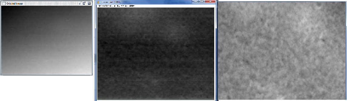
Thanks for the reply. Actually I am myself little bit confused about the same thing that how will it differentiate between the actual data and the artifact. And how much actual data will get lost in following such an approach. I have already removed the non uniform background from the original image by fitting a plane on it and subtracting from the original image. I have attached the sample image. The image on the left most is what I get from AFM and the image in the middle is what I get after correcting the background and the image on the right is my target. There are even many plugins available to perform such an operation. Now i am looking for some algorithm to bring the image to the same level. One approach is by subtracting the median from each line individually but i couldn't find much reading material about it that could explain why will it not remove the actual data and only the artifacts. i will just try to subtract the median same way u mentioned and will let u know if i have some positive results. May be for that I have to modify the median filter to some extent. Thanks Again Ahsan |
|
|
In reply to this post by Daniel James White
Dan
Thanks for the reply. I really appreciate that. No doubt Turku is really a nice city. Specially this year it was being the European capital :D ... but unfortunately this is my last week in Finland for this year as I am coming to Germany for a period of six months. Lets see how much I like Munich as compared to Turku :) . I have tried the Fourier domain filter and it worked. But now I am just more curious to know about the drawbacks of each approach as compared to the other one. Which one will make me loose more actual data. It would be really nice for me to understand the actual working and algorithm behind the median approach and to know how will it differentiate between the actual data and the artifact. I get the Images from AFM and actually we should consider replacing or getting the equipment serviced if the data gets worse. I have already conveyed your advise to my supervisor. Thanks again Regards Ahsan |
|
|
In reply to this post by ashamim
|
|
|
Hi,
I don't know much about AFM but the so called original is for sure already processed or result of an inadequate scan either by scan parameters or broken or used cantilever. Before throwing away the AFM you should look into the description and save your data as raw format! Regards Karsten Am 23.08.2011 um 11:32 schrieb ashamim: > http://imagej.588099.n2.nabble.com/file/n6715418/sample.jpg > > ----- > Ahsan > -- > View this message in context: http://imagej.588099.n2.nabble.com/Leveling-Image-tp6710546p6715418.html > Sent from the ImageJ mailing list archive at Nabble.com. Karsten [hidden email] |
|
|
In reply to this post by ashamim
On Tuesday 23 Aug 2011, Ahsan wrote:
> I have already removed the non uniform background from the original image > by fitting a plane on it and subtracting from the original image. Why you to fit a plane and subtract it before correcting the image bands? Doesn't that change the topography of the image? and doesn't this also change the offset that needs to be corrected so now it is not a constant offset along the line anymore? > subtracting the median from each line individually but i couldn't find > much reading material about it that could explain why will it not remove > the actual data and only the artifacts. If you offset according to the median of all the data in the line (as opposed to a known reference that should be originally constant across lines, such as a portion of background) this offset is not guaranteed to be the right one unless the image is quite homogeneous. If the data indeed goes up, the median (and hence the offset) will probably go up too, but the line perhaps does not need to be made darker than it is just because the median is large. Sorry I do not have any further suggestions other than improving the scanning quality. Maybe there is a standard method used in AFM, but I am not familiar with this. Cheers Gabriel |
|
|
Hi Ahsan, Gabriel,
in principle it is true that one should avoid a posteriori background subtraction, but that's not so easy in scanning probe microscopies like AFM. It can sometimes happen that the tip changes by interaction with the surface, and this gives a step in the image. By the way, subtracting a plane does not hurt at all as long as the slope is only a few degrees or less, which is usually the case. A normal AFM tip won't show you steep slopes anyhow, so subtracting a plane is equivalent to slighly tilting the sample to make its surface parallel with the x, y scan directions. (To put it into perspective for the optical microscopy people: in AFM images one usually has image sizes of several micrometers, but a vertical scale of a few dozen nanometers or even less) I'll paste below a quickly written plugin that subtracts the median from each line. Of course, this is not perfect, because you never know what the background should be, but better than having steps due to tip changes in the image. Line-by-line subtraction should be a reasonable approach if the surface is on average flat at length scales comparable to the image width. Michael ________________________________________________________________ import ij.*; import ij.process.*; import ij.plugin.filter.*; /** This plug-in filter subtracts from each line the median of * the pixel values in the line. * Selections (regions of interest) are ignored. * * For background subtraction of scanning probe microscopy images * with uneven background due to tip changes. * * Copyright: This code is distributed under the terms of the GNU General Public License * www.gnu.org/copyleft/gpl.html * * Author: Michael Schmid, 23-Aug-2011 */ public class Subtract_Line_Median implements PlugInFilter { private final static int flags = DOES_ALL | CONVERT_TO_FLOAT | PARALLELIZE_STACKS; private float offset = 128f; /** Method to return types supported etc. * @param arg unused here * @param imp The ImagePlus containing the image or stack * @return Code describing supported formats etc. */ public int setup(String arg, ImagePlus imp) { if (imp != null) { if (imp.getType() == ImagePlus.GRAY16) offset = 32768f; else if (imp.getType() == ImagePlus.GRAY32) offset = 0f; } return flags; } /** This method is invoked for each slice during execution * @param ip The image subject to filtering. */ public void run(ImageProcessor ip) { int width = ip.getWidth(); int height = ip.getHeight(); float[] pixels = (float[])ip.getPixels(); int half = width/2; float[] aboveBuf = new float[width]; float[] belowBuf = new float[width]; float median = offset; //initial guess for (int y = 0; y<width; y++) { int nAbove = 0, nBelow = 0; for (int p=y*width; p<(y+1)*width; p++) { float v = pixels[p]; if (v > median) { aboveBuf[nAbove] = v; nAbove++; } else if (v < median) { belowBuf[nBelow] = v; nBelow++; } } if (nAbove>half) median = RankFilters.findNthLowestNumber(aboveBuf, nAbove, nAbove-half-1); else if (nBelow>half) median = RankFilters.findNthLowestNumber(belowBuf, nBelow, half); for (int p=y*width; p<(y+1)*width; p++) pixels[p] += offset-median; } //for y } } ________________________________________________________________ On 23 Aug 2011, at 12:29, Gabriel Landini wrote: > On Tuesday 23 Aug 2011, Ahsan wrote: >> I have already removed the non uniform background from the >> original image >> by fitting a plane on it and subtracting from the original image. > > Why you to fit a plane and subtract it before correcting the image > bands? > Doesn't that change the topography of the image? and doesn't this > also change > the offset that needs to be corrected so now it is not a constant > offset along > the line anymore? > >> subtracting the median from each line individually but i couldn't >> find >> much reading material about it that could explain why will it not >> remove >> the actual data and only the artifacts. > > If you offset according to the median of all the data in the line > (as opposed > to a known reference that should be originally constant across > lines, such as > a portion of background) this offset is not guaranteed to be the > right one > unless the image is quite homogeneous. > > If the data indeed goes up, the median (and hence the offset) will > probably > go up too, but the line perhaps does not need to be made darker > than it is > just because the median is large. > > Sorry I do not have any further suggestions other than improving > the scanning > quality. Maybe there is a standard method used in AFM, but I am not > familiar > with this. > > Cheers > > Gabriel |
|
|
In reply to this post by ashamim
Here is the idea I was thinking of.
The first macro loads the Lena image and creates random offsets for the scan lines to simulate a scan with artifacts. //-----------8<--------------- run("Lena (68K)"); setBatchMode(true); a="_test_"; run("Duplicate...", "title="+a); run("8-bit"); run("Reslice [/]...", "output=1.000 start=Top"); selectWindow("Reslice of "+a); for(i=1;i<=nSlices;i++){ setSlice(i); r=random()*32; run("Add...", "value="+r+" slice"); } run("Reslice [/]...", "output=1.000 start=Top"); setBatchMode(false); //-----------8<--------------- This other macro creates a ROI over the more or less constant background (the clear part on the left of the image) and compensates for a difference between the average background and that of the individual lines. //-----------8<--------------- makeRectangle(42, 0, 13, 512);// Lena's background getRawStatistics(nPixels, mean); run("Select None"); print(mean); for (y=0;y<512;y++){ tot=0; for (x=42;x<55;x++){ tot=tot+getPixel(x,y); } tot=tot/13; offset=mean-tot; //print(offset); for (x=0;x<512;x++) putPixel(x, y, getPixel(x,y)+offset); } updateDisplay() //-----------8<--------------- This works well if the background is constant. In the Lena image, the background varies slightly so the result has a bright line relatively visible because the background has a darker pixels in that particular region. The problem is that the example given earlier does not have such a constant background region for reference. Cheers Gabriel |
|
|
Hello Gabriel And Michael
Thank you so much for your help and thanks for clarifying what difference does it make if I perform the line correction after the plane correction. I myself noticed that the only change comes in the mean value of the image and that might be because i was normalizing the image after subtracting the plane to get rid of the negative value. Other than that the images retains all its properties going any way around. Both the macro and the plugin are quiet useful for me. And subtracting the median line by line actually give me what I was looking for. @ Michael Do u think there is some possible way to get rid of these steps from the base ? I mean so that they shouldn't even come from the AFM. Regards Ahsan
|
|
|
On 24 Aug 2011, at 11:53, ashamim wrote:
> ... > @ Michael Do u think there is some possible way to get rid of these > steps > from the base ? I mean so that they shouldn't even come from the AFM. Hi Ahsan, well, I am not an AFM expert, it depends on what operating mode you use, and also on the samples. In contact mode, you should use a contact force as low as possible and also avoid scanning at too high speeds, so the feedback loop can react in time when the tip reaches a high protrusion. Also in intermittent contact mode (tapping mode), you can choose an amplitude setpoint that is closer to the free amplitude, to reduce the contact force, and also make sure the scanning speed is not too high. If the problem is due to the tip picking up particles from the surface (typically, the tip becomes longer, so it looks like an upwards step in the image): If and the sample allows it, try to remove all particles by suitable preparation: rinse in a solvent and blow the solvent off, remove particles by strong blowing with dry nitrogen or (better) CO2 show cleaning, etc. I'd propose that you talk to someone who has experience in AFM on samples like yours. Michael |
«
Return to ImageJ
|
1 view|%1 views
| Free forum by Nabble | Edit this page |